
How To Mount A SingleTact Flexible Force Sensor?
Back to Application Notes
1. Introduction
A flexible force sensor such as SingleTact is an ultra-thin sensor designed to measure force applied perpendicularly across its active sensing region, and it delivers accurate results only when the sensor is mounted to avoid bending and shear. There are a number of ways to integrate SingleTact force sensors into your application, and each comes with its own mounting challenges, so deciding on the best method is not always straightforward. SingleTact thin force sensors are ready to use and cost effective, making them suitable for a wide range of easily integrated applications.
This note is written for engineers, designers, and developers who need precise force measurement and reliable integration in real products, test setups, or early-stage device development. It focuses on the practical parts of implementation that affect accuracy, durability, and ease of assembly: sensor positioning, mechanical constraints, mounting the sensor with tape or glue, mounting the associated electronics, using tail extenders when more mounting flexibility is needed, and choosing the communication interface for reading out the pressure data.
The SingleTact anatomy consists of three main parts: the SingleTact force sensor, the SingleTact electronics, and the communication interface for reading out the pressure data. There are mounting considerations to each part that will be covered in this note. Below, a 15mm SingleTact force sensor and a standard electronics board is depicted.

2. Capacitive Force Sensor Mechanical Consideration
SingleTact is a flexible, thin force sensor: its construction consists of a top electrode, a sensor dielectric, and a bottom electrode, sandwiched together with adhesive. Therefore, it is best to avoid applying shearing forces to the sensor, and instead applying direct forces perpendicularly and evenly across the sensor head.
In real-world measurement setups, a flexible force sensor may still experience some bending, so the mounting method affects performance as much as the structural design — poor mounting is one of the most common sources of unnecessary mechanical stress on the sensor. Sensitivity, linearity, and response speed are key performance parameters influenced by mechanical loading and mounting, and correct mounting is what protects the sensor's high sensitivity and keeps its response fast and consistent.

Sensor Bending Radius & Loading Limits
Another action to avoid is bending the sensor head whenever possible, as bending causes one electrode to be in compression while the other is in tension, leading to shear stress between the two electrodes. If bending is necessary to fit the sensor into your application, ensure that the circular portion (the active sensing region) remains as flat as possible, while applying the bend along the tail end of the sensor. Maintain a bend radius greater than 300 mm for the sensor and greater than 3 mm for the tail.
Loading limits also matter for a safe mount: keep applied pressure below roughly 3x the sensor's rated full-scale range (FSR) to avoid damaging it. Because the sensor measures compression, avoid mounting methods that could place the sensing area under tension rather than direct load — an output reading below 0.5V can indicate the sensing area is being pulled into tension, which risks damaging the sensor's internal structure.
3. Mounting The SingleTact Force Sensor
The SingleTact force sensor is the first and most critical component to position and mount, due to its orientation requirements. Before beginning, choose the sensor and mounting approach based on your load distribution and the target surface geometry, and consider whether the selected sensor properly suits your application or if some modifications are required. Explore SingleTact's Sensor Selector page and click on the "What size should I get?" button for more information. If your load distribution is awkward or uneven, you may need to consider designing a custom load distributor for your application before moving on to mounting. The flexible force sensor format is well suited to complex curved surfaces because it is ultra-thin and lightweight, adding negligible mass, but it still needs even load transfer at the sensing area.
Another consideration is moisture. SingleTact force sensors are suitable for most environments, except humidity, which may affect sensor performance. If your application will be exposed to moisture or perspiration, use or create some sort of polyurethane sheath to encase the sensor in beforehand. This could be as simple as using a sandwich bag or a trading card sleeve. You could also use a heat sealer to develop a custom encasement solution.
Tape and glue each carry their own advantages depending on the mounting environment and how accessible the target surface is.
Double-Sided Tape
There are a number of methods for mounting the SingleTact force sensor: double-sided tape, single-sided tape, and glue. Custom enclosures and other fastening methods are also possible, but will not be discussed here. Double-sided tape is a good solution for easily mounting a sensor to a project. It is best to use a thin but strong tape, as a more spongy tape will interfere with sensor performance.
Begin by connecting the SingleTact force sensor to the SingleTact electronics.
Cut a small piece of double-sided tape (just enough to cover the head of the sensor) and place it on the sensor head, bottom side.
Remove the protective backing from the double-sided tape, and mount the sensor. Take into consideration where the electronics will be mounted afterwards.
Single-Sided Tape
Single-sided tape follows a similar mounting procedure as above, but there are some considerations to keep in mind regarding the type of tape used. Stiff tapes like packaging tape is not recommended in most applications, as it can adversely affect the sensor readings by adding unnecessary rigidity to the mount; opt instead for more conforming tapes like PTFE or PVC tape. These flexible tapes will also conform better to abnormal geometries than rigid tapes would. Compared to a stiff clear tape, PTFE tape conforms far more readily to curved or irregular surfaces, as shown in the two images below.

Glues
Quick-setting glues such as hot glue or epoxy should be considered only when the use of tape is not suitable. Applications where the SingleTact force sensor needs to be positioned in a narrow slot makes the use of tape difficult or impossible, as the tape will catch or prevent the sensor from being inserted. For a sensor to be placed into such a position, glue allows the user to position the sensor as desired, and then it sets once in place.
For best results with glue, apply just enough glue to the center of the sensor head to create an even layer over the surface. Once hardened, the glue will act as a force distributor, as shown in the left image below. This even load transfer helps preserve high stability and a wide detection range for precise force sensing. Avoid using an excessive amount, as the glue may curl around the sensor and create a depression, as depicted exaggeratedly in the right image below. Instead of exerting pressure on the sensor itself, the application ends up exerting pressure on the hardened glue around the sensor, which is non-ideal.

One major drawback of glue is that the sensor is likely unsalvageable once mounted. If the sensor needs to be removed afterwards, the user risks damaging the sensor or the device the sensor is glued to.
Lastly, do not use any glues that outgas such as super glue, as this will damage the surface / internals of the SingleTact force sensor or make it brittle.
Tip: Once mounting is complete, power the system on with the sensor unloaded (no pressure applied), so its baseline can register correctly before use.
4. Mounting the SingleTact Electronics
The SingleTact electronics come in two forms: standard electronics, and USB electronics. If you are using standard electronics for your application, be aware that the standard electronics feature 0.1" through-hole header pins, which means you will have to take into account the protruding pins on the underside of the board. The USB electronics board on the other hand is essentially flat. Other than this difference, mounting these electronics is similar and relatively simple, and there are two suggested methods for doing so: double-sided tape, and screw mounting.
Double-Sided Tape
While a thin double-sided tape is recommended for the SingleTact force sensor mounting, a thicker double-sided tape is optimal for mounting SingleTact electronics. The purpose is two-fold: a thicker tape will allow the rigid electronics board to conform to uneven surfaces better, and will allow the pins on the standard electronics board to clear surfaces easier. Position the electronics so that there is little to no stress on the sensor.

Screw Mounting
Both the standard electronics and the USB electronics boards feature screw hole cutouts, which can be used for mounting the boards to devices that accept screws (wood, plastic, sheet metal, etc). As with the double-sided tape solution, keep in mind the clearance of the through-hole pins on the standard electronics board. In the image below, a #2 thread-forming plastic screw is used to mount a standard electronics board to a 3D-printed device. Note that the board overhangs to allow the through-hole pins to clear the surface and allow for a flat mount.

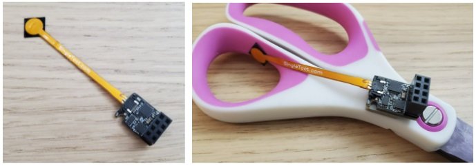
Tip: If your application has moving parts, such as the scissor example in the images above, try to mount the electronics on the same moving piece as the sensor to minimize movement along the length of the sensor.
5. The Tail Extender
The tail extender offers much more mounting flexibility to the user, and not just because of the 6" of extra length. The tail extender is able to bend and conform to an application much better than a SingleTact force sensor alone would, since the tail extender is 67% thinner than the SingleTact force sensor, and is, therefore, less prone to breakage. This added flexibility is especially useful in wearable electronics, robotics, industrial automation, and health monitoring applications, or other space-constrained devices where unobtrusive routing matters. This also allows the user to position the sensor and electronics almost exclusively of each other, and transfer the mechanical strain away from either end.
When routing the tail extender, avoid touching it during operation and keep it clear of earthed or grounded shielding nearby, since either can introduce interference into its signal traces.
In the application example below, a SingleTact force sensor is mounted to the plunger head of a dispenser, while the electronics is mounted on the cap end. Ideally, the sensor and electronics would both be mounted together on a moving part, but when the mounting surface is as small as this, sometimes it is not possible to do so. In this configuration, when the plunger is depressed, this action creates a bending force across the length of the SingleTact force sensor and puts strain on the FFC connector of the electronics board. This motion also puts considerable stress on the contact end of the sensor and stiffener.

With a tail extender, much of the mechanical stress and strain mentioned above is alleviated. The SingleTact force sensor experiences much less flexing and bending, and those forces are instead transferred across the tail extender that connects to the electronics mounted off below.

6. Force Sensing Communication Interfaces
There are three data output formats: I2C, voltage, and USB. These formats sit on top of the sensor's underlying sensing mechanism: compared to similar technologies such as FSRs and strain gauges, SingleTact uses capacitive sensing with its own readout electronics to provide I2C, voltage, or USB output.
The first two formats are available on the standard electronics board in the form of 0.1" header pins. A major cable routing consideration is that the female pin header block is perpendicular to the surface of the board, so the wires will protrude considerably from the surface of your device.
In contrast, with the third format (available on the USB electronics board), the USB data exits parallel to the plane of the board, allowing for a much lower profile installation. See the comparison photo below with the standard electronics in the background and the USB electronics in the foreground. If your application requires a low-profile installation, consider using the USB interface instead.

Mounting either cable interface is straightforward as long as common sense is followed. Here is a short list of recommendations:
If movement is expected, fasten the cable(s) with tape or zip ties to prevent accidental removals and create strain relief.
Use cable management clips to route longer cable runs to your controller.
If using standard electronics, ensure that the pins do not pull out accidentally.
Place electronics in a location that allows the connections to avoid accidental catching.
Ready to find the right sensor for your application?
Browse SingleTact Sensors